|
MAIN
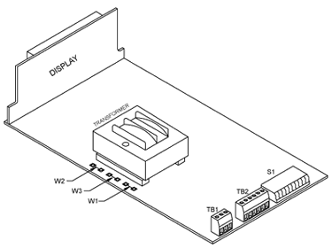
BOARD POWER JUMPERS
Caution:
The meter has no
power-on switch,
so it will be in
operation mode as
soon as you apply
power. Typically
the meter is shipped
per order (per the
part number requested)
and no modification
is necessary. However,
if you want to check
voltage jumpers,
or to change from
115 Vac to 230 Vac
(refer to Figure
3-8). Verify that
a duplicate set of
wire jumpers are
not on the bottom
side of the transformer.
Disconnect the
power from the unit
before proceeding.
1. Remove
the main board from
the case.
2. Locate
the wire jumpers
W1, W2 and W3 (located
near the edge of
the main board alongside
the transformer).
3. If your
power requirement
is 115 Vac, install
solder jumpers W1
and W2, but do
not install jumper
W3. If your power
requirement is 230
Vac, install solder
jumpers W3, but do
not install jumpers
W1 or W2.

Figure 3-8.
Main Board Jumpers
(W1, W2, W3)
AC
Power Failure Provision
To store a total count
in the nonvolatile
memory if an ac power
loss occurs set the
S1-10 switch to "open".
When ac power resumes
the meter displays
the total at the time
of the power loss,
and then resumes totalizing.
DC
Power/Backup Battery
Provision
You may power the meter
from an external dc
power supply, or an
external battery. The
typical current requirement
is 260 mA at 7.5 to
13 Vdc to maintain
full operation and
meter display when
no option board is
installed. You can
shut off the display
without affecting any
meter functionality
by setting the S1-
10 switch to open.
Shutting off the digital
display reduces the
current requirement
to 30 mA (if option
boards are installed,
add 180 mA for an analog
output board, 120 mA
for a dual-relay board,
and 20 mA for an RS232
board).
Caution:
If the S1-10 switch
is in the "closed"
position, the meter
does not detect any
power loss (ac or dc),
and therefore will
not load the display
data into the nonvolatile
memory. In this case
the Total is loss when
both ac and dc power
are lost.

Figure 3-9. DCPower/Battery
Backup
MOUNTING
THE METER

Figure
3-10. Meter
- Exploded
View
|

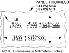
Figure 3-11
Panel
Cut-Out
|
1. Cut a hole
in your panel, as shown
in Figure 3-10. For
specific dimensions
refer to Figure 3-11.
2. Insert the
meter into the hole.
Be sure the front bezel
is flush to the panel.
Refer to
Table 6-1 for summary
list of menu configurations.
SELECTING
MAIN MENU ITEMS
1. Press the
MENU button.
The meter shows a main
menu item. Continue
to press the MENU
button to scroll through
main menu items.
2. Once the
desired main menu item
shows, press the  SET button to
show the item's current
value or the active
sub-menu item.
SELECTING
SUB-MENU ITEMS
1. Select main
menu item.
2. Once the
meter shows the correct
main menu item, press
the  SET button.
The meter shows either
the active sub-menu
item or the main menu
item's current value.
3. If the meter
shows an available
sub-menu item, press
the  ADV button to
show the sub-menu item's
current value.
Note: The main
menu items "OFFSET"
and "COnFIG" do not
have sub-menus. If
you press the  SET button when
the meter shows either
of these items, the
meter will show the
current number value.
4. Press the
 SET button to
change the flashing
number value. The left-most
digit (above the RECALL
button) may be set
to a minus sign. Also,
press the
  SET button to
change the decimal
point position.
5. Press the
 ADV button to
change which digit
is flashing.
SAVING
CHANGES
You may store (save)
meter changes in the
volatile and nonvolatile
memory. Remember you
cannot store changes
in the nonvolatile
memory without first
storing them in the
volatile memory.
To store changes
in the nonvolatile
memory, follow these
steps:
1. Make required
changes, using the
 ADV button to
show current values
and also to move from
left to right through
the digital display.
The digit or value
that may be changed
will flash. Use the
 SET button to
change the function,
number value or decimal
point of the flashing
item.
2. Press the
MENU button
until the meter shows
"noStor".
3. Press the
 SET button.
The meter shows "StorE".
4. Press the
MENU button
to store the changes
to the nonvolatile
memory. If power loss
occurs, or meter is
hard reset these changes
stay in the meter's
memory.
To store changes
in the volatile memory,
follow these steps:
1. Make required
changes, using the
 ADV button to
show current values
and also to move from
left to right through
the digital display.
The digit or value
that may be changed
will flash. Use the
 SET button to
change the function,
number value or decimal
point of the flashing
item.
2. Press the
MENU button
to store changes to
the volatile memory.
3. Press the
RESET button
to operate the meter
from the volatile memory. |